HomeEngineered ProductsADC for Medical DeviceAnalog-to-Digital Converter (ADC)
Analog-to-Digital Converter (ADC)

Analog-to-Digital Converter (ADC)

Home Archives

Analog-to-Digital Converter (ADC)

CONTACT NOW

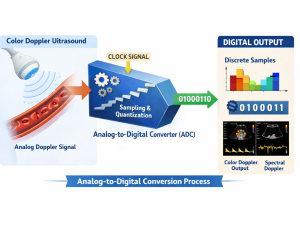
Overview of the Role of ADC in Color Doppler Systems

In a Doppler ultrasound system, the signal received from the probe is an analog signal with very small amplitude, typically in the MHz range. This signal carries information about blood flow velocity and direction through the Doppler effect.

The ADC performs three core functions:

  • Sampling the continuous signal over time
  • Quantization into discrete levels
  • Encoding into digital data

The performance of the ADC directly impacts:

  • Doppler velocity resolution
  • System dynamic range
  • Noise floor
  • Accuracy of the Doppler spectrum

Detailed Structure of ADC Components

1. Analog Front-End (AFE)

This is the pre-processing stage before the ADC and is critically important.

Low Noise Amplifier (LNA)

  • Amplifies very weak signals from the probe (~µV to mV)
  • Requirements:
    • Ultra-low noise figure (< 2 dB)
    • High linearity (high IP3)

Poor design at this stage will significantly degrade the overall system SNR.


Variable Gain Amplifier (VGA)

  • Adjusts gain dynamically (Time Gain Compensation – TGC)
  • Compensates for signal attenuation with depth

This is essential for maintaining uniform image quality across different depths.


Anti-aliasing Filter (AAF)

  • Low-pass filter placed before the ADC
  • Removes high-frequency components that could cause aliasing

This is a common design pitfall if not properly implemented or if the cutoff frequency is incorrectly selected.


2. Sample and Hold (S/H)

  • Samples the signal at discrete time instances
  • Holds the sampled value stable during conversion

Technical requirements:

  • Extremely low aperture jitter (in femtoseconds range)
  • High bandwidth (tens of MHz)

Jitter performance is critical in Doppler systems as it directly affects frequency accuracy.


3. Core ADC Architecture

Depending on the design, different ADC architectures can be used:

Pipeline ADC (most common)

  • High speed (20–100 MSPS)
  • Resolution: 12–16 bits

Best suited for Doppler ultrasound applications.


SAR ADC

  • High accuracy
  • Low power consumption
  • Limited speed


Sigma-Delta ADC

  • Very high resolution
  • Not suitable for high-frequency Doppler signals


4. Quantizer & Encoder

  • Converts analog signals into digital binary codes
  • Typical resolution: 12–16 bits

Higher resolution provides greater dynamic range


5. Clock System

  • Clock generator + PLL
  • Controls the entire sampling process

Requirements:

  • Low phase noise
  • Ultra-low jitter (< 1 ps)


6. Digital Interface

  • LVDS / CMOS outputs
  • Interface to FPGA or DSP

In modern systems:

  • ADC → FPGA → Beamforming → Doppler Processing


Critical Considerations in ADC Board Design and Manufacturing

1. PCB Layout – Determines 50% of Success

Key principles:

  • Separate Analog Ground and Digital Ground
  • Keep analog signal traces as short as possible and properly shielded
  • Avoid crossing between clock lines and analog signals

A poor layout can result in a 20–30 dB loss in SNR.


2. Power Supply Design

  • Use low-noise LDO regulators for AFE and ADC
  • Separate power domains:
    • Analog supply
    • Digital supply
    • Clock supply

Power noise is one of the primary causes of jitter and distortion.


3. EMI/EMC Compliance

Medical devices must meet strict standards:

  • IEC 60601-1-2
  • Proper shielding
  • Input power filtering


4. Thermal Management

  • High-speed ADCs generate significant heat
  • Requires:
    • Heatsinks
    • Copper planes
    • Thermal vias

Temperature variations directly affect ADC drift and accuracy.


5. Calibration & Matching

  • Offset calibration
  • Gain calibration
  • Timing alignment

Even small mismatches can lead to incorrect blood flow velocity measurements.


6. Component Selection

Typical ADC vendors include:

  • Texas Instruments
  • Analog Devices
  • Maxim Integrated

Selection criteria:

  • High ENOB (Effective Number of Bits)
  • Good SFDR (Spurious-Free Dynamic Range)
  • Reasonable power consumption

Reviews

There are no reviews yet

Add a review
Analog-to-Digital Converter (ADC) Analog-to-Digital Converter (ADC)
Rating*
0/5
* Rating is required
Your review
* Review is required
Name
* Name is required
Add photos or video to your review
PCES - AI Support
Contact